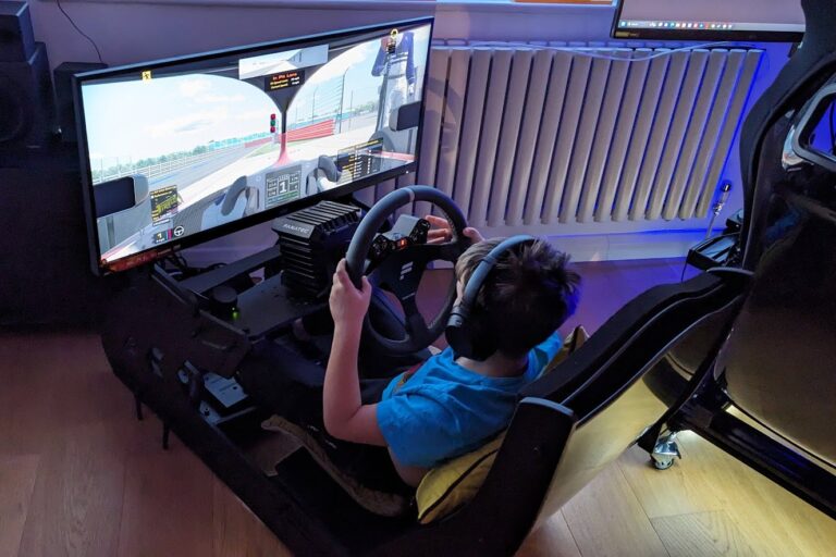

I’m a sim racer and amateur racer with a passion for Motorsport, good racecraft and the technical and setup aspect of sim racing.
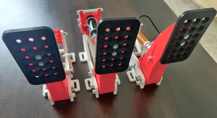
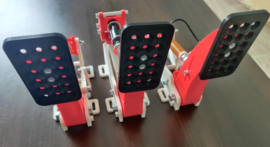
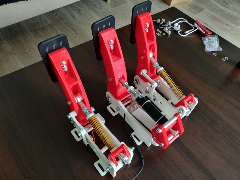
Featured Image: Finished DIY load cell pedals with 3D printed components
After spending countless hours testing commercial load cell pedals, I’ve discovered something remarkable: you can build pedals that rival £500+ commercial options for under £150. The secret? Understanding the engineering principles and having the right guidance.
This amazing guide from DiySimStudio walks you through building pro-grade load cell pedals using 3D printing and readily available electronics. Whether you’re upgrading from potentiometer-based pedals or starting fresh, I’ll show you exactly how to create pedals that deliver genuine muscle memory braking.
Quick Navigation
Why Load Cells Transform Your Sim Racing
Essential Components and Tools
Building the Throttle and Clutch
Constructing the Load Cell Brake
Electronics and Calibration
Troubleshooting Common Issues
Advanced Modifications and Upgrades
Final Thoughts and Performance
Resources and Links
Why Load Cells Transform Your Sim Racing
Before diving into the build, let’s address this: why bother with load cells?
The answer lies in how our brains process information. When you brake in a real car, you’re not thinking about pedal position, you’re modulating pressure. Load cells measure force, not travel, which fundamentally changes how you interact with the brake pedal. This is an action that you can bake into muscle memory, so, you improve with time.
The Engineering Behind Load Cells
A load cell is essentially a transducer that converts force into an electrical signal. When you press the brake pedal, you’re deforming a metal beam with strain gauges attached. These gauges change resistance proportionally to the applied force, creating a measurable voltage difference.
What makes this brilliant for sim racing is the linearity and repeatability. A 50kg press will always produce the same output, regardless of temperature, pedal position, or how many hours you’ve been racing. This consistency is what builds muscle memory.
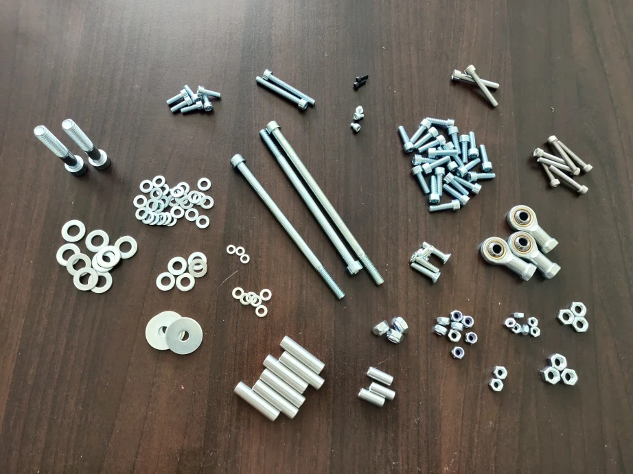
Essential Components and Tools
Let’s start with what you’ll need according to the video:
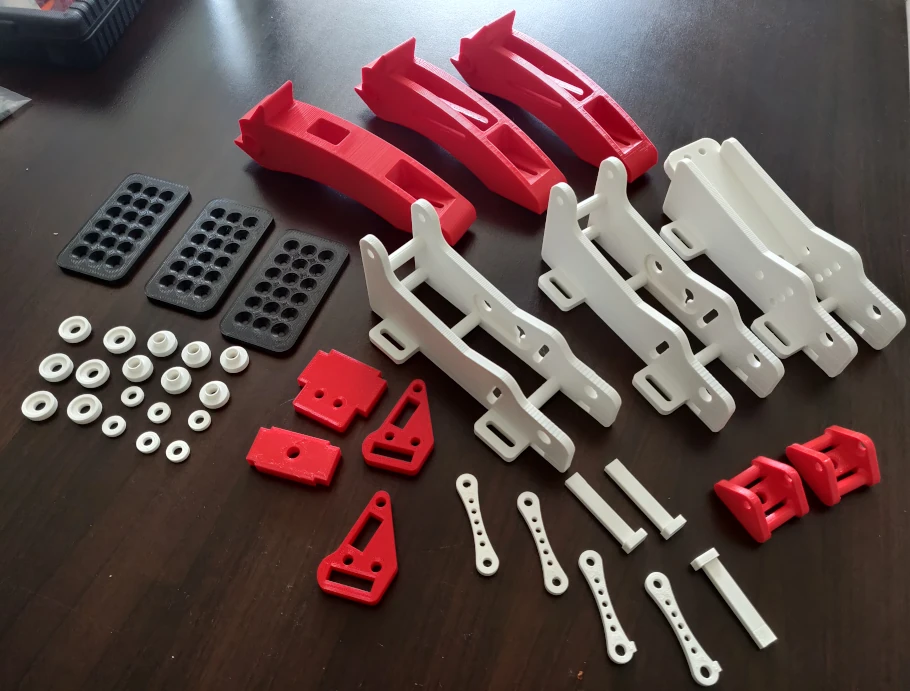
3D Printed Parts
The beauty of this design lies in its accessibility. If you don’t own a 3D printer, services like Treatstock can print the parts for around £40-60.
When ordering, specify:
- Material: PETG or ABS (avoid PLA for the brake components)
- Infill: 80% for structural parts, 100% for the brake spring support
- Layer height: 0.2mm for the best strength-to-print-time ratio
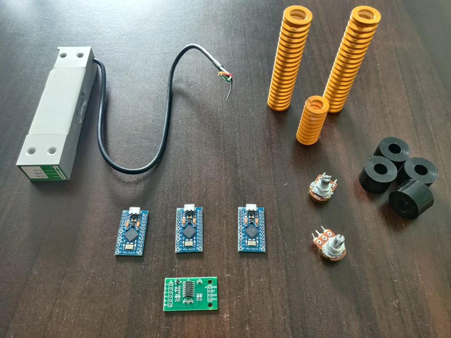
Electronics Shopping List
Here’s where things get interesting. You have two paths: the DIY Arduino route or plug-and-play controllers.
Arduino Route (£35-45 total):
- Arduino Leonardo or Pro Micro (£15-20)
- HX711 Load Cell Amplifier (£5) – get the purple PCB version, not the green
- 120kg beam load cell (£15-20)
- 2x 10k potentiometers for throttle/clutch (£10)
Plug-and-Play Route (£80-120):
- Leo Bodnar BU0836-LC 12-bit (£65) or LC-USB 16-bit (£85)
- 120kg load cell (£15-20)
- 2x P260 potentiometers (£15 each from Leo Bodnar)
Having built both versions, I’d recommend starting with Arduino if you’re comfortable with basic soldering. The setup process takes an extra hour, but you’ll save £50+ and gain valuable understanding of how everything works.
Hardware Components
The spring selection significantly impacts pedal feel:
- Throttle/Clutch: 90mm x 20mm springs (6-8 N/mm rate)
- Brake: 30mm x 20mm spring (15-20 N/mm rate)
- Elastomers: 85A and 90A durometer bushings (minimum 2 of each)
Pro tip: Order extra elastomers in different durometers. Mixing 85A and 95A bushings lets you fine-tune the brake feel from progressive to ultra-stiff.
Building the Throttle and Clutch
We’ll start with the simpler potentiometer-based pedals. The throttle and clutch use identical construction, so you’re essentially building the same pedal twice.
Step 1: Fixed Part Assembly
Begin by mounting the M6x40 spacer into the fixed part. This spacer acts as your pedal stop, preventing over-rotation and protecting the potentiometer. Use a drop of medium-strength threadlocker here; you don’t want this coming loose mid-race.
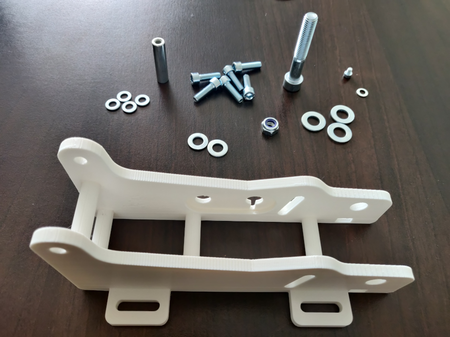
Step 2: Mobile Part and Footplate
The mobile part houses your footplate, which can be adjusted for different driving positions. When mounting the female rod end, ensure it moves freely without binding. Any resistance here translates directly to inconsistent pedal feel.
A critical detail often overlooked: the footplate has multiple mounting positions. Start with the middle position, you can adjust later based on your seating position and leg length.
Step 3: Spring Installation
Here’s where pedal feel comes alive. The spring doesn’t just provide resistance; it determines the entire force curve of your pedal.
When installing:
Visit Our Sponsors
- Insert the spring into the female rod end first
- Compress slightly and align with the spring support
- The spring should have 2-3mm of preload when the pedal is at rest
Step 4: Potentiometer Magic
The potentiometer mounting is where precision pays dividends. You’re creating a lever system that translates pedal rotation into electrical resistance changes.
Key points for potentiometer installation:
- Use 2-3 washers between the lever and mobile part to prevent binding
- The potentiometer should be centred in its rotation at pedal rest
- Route cables through the dedicated management hole to prevent snagging
I’ve seen many builds fail here due to over-tightening. The lever connection needs to be snug but still allow free movement. If you feel any notchiness when moving the pedal, you’ve overtightened.
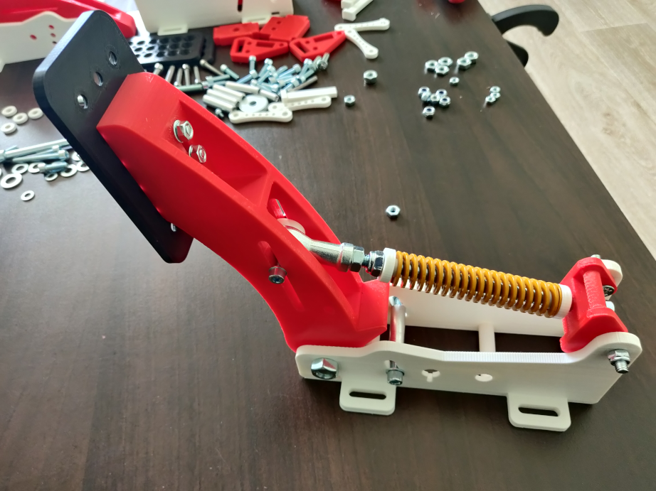
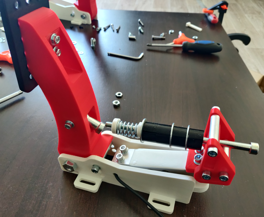
Constructing the Load Cell Brake
Now for the main event. The brake pedal is where this design truly shines, delivering a feel that rivals commercial units costing five times as much.
Understanding Load Cell Mounting
The genius of this design lies in its vertical orientation of the load cell. By mounting the load cell perpendicular to the pedal movement, we eliminate side-loading issues that plague cheaper designs. This is crucial; even slight off-axis forces can damage budget load cells.
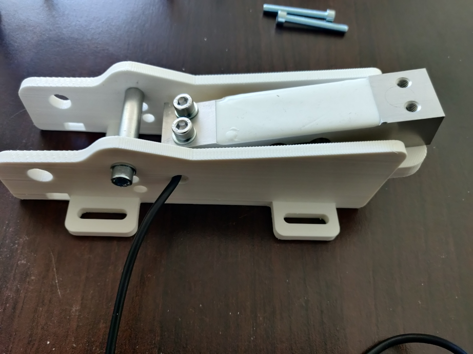
The Critical Load Cell Installation
Follow this sequence exactly:
- Thread the load cell cable through the dedicated hole before mounting
- Align the load cell’s arrow with the force direction (towards the pedal)
- Use M6 bolts with flat washers to distribute load evenly
- Tighten in a cross pattern to prevent warping
Here’s a detail that transformed my brake feel: apply a thin layer of silicone grease to the load cell contact surfaces. This prevents micro-movements that can cause dead zones in your brake response.
Spring and Elastomer Stack
The brake feel comes from your elastomer stack configuration. After extensive testing, here’s my recommended starting point:
- Bottom: 90A elastomer (firm base)
- Middle: 30mm brake spring
- Top: 85A elastomer (progressive feel)
This configuration provides initial soft travel (about 10mm) before hitting progressive resistance. The beauty is in the adjustability, swap elastomer positions or add extras to completely transform the pedal character.
Electronics and Calibration
With the mechanical build complete, it’s time to bring your pedals to life. This is where many builders stumble, but follow these steps and you’ll be racing within an hour.
Arduino Setup: The Smart Choice
If you’ve chosen the Arduino route, you’re in for a treat. The community has created bulletproof code that just works.
Essential software setup:
- Install Arduino IDE (version 1.8.x recommended, not 2.0)
- Add the Joystick library by MHeironimus
- Install the HX711 library by Bogdan Necula
- Download the proven pedal sketch from the DIYSimStudio resources
Wiring That Works
Here’s the wiring diagram that’s proven reliable across hundreds of builds:
Load Cell to HX711:
- Red → E+
- Black → E-
- White → A-
- Green → A+
HX711 to Arduino:
- VCC → 5V
- GND → GND
- DT → Pin 4
- SCK → Pin 5
Potentiometers to Arduino:
- Outer pins → 5V and GND
- Centre pin → A0 (throttle), A1 (clutch)
Pro tip: Use different coloured wires for each pedal. When you’re troubleshooting at 2 AM, you’ll thank yourself.
Calibration: The Final Touch
Calibration separates good pedals from great ones. Here’s my proven process:
- Initial setup: With pedals at rest, note the raw values in the Arduino serial monitor
- Full throw test: Press each pedal fully and record maximum values
- Load cell scaling: Apply 10kg of force (use luggage scales) and adjust the scale factor until the output reads 10000
- Dead zone elimination: If experiencing brake dead zones, slightly loosen the M6 nuts under the load cell mount
Troubleshooting Common Issues
After helping dozens of builders, these are the issues that crop up most frequently:
Issue 1: Reversed Load Cell Pressure
Symptom: Brake shows 100% when released, 0% when pressed.
Solution: In your Arduino sketch, find this line:loadCellValue = scale.get_units();
Change it to:loadCellValue = -scale.get_units();
The minus sign reverses the output. Simple but effective.
Issue 2: Arduino Not Recognised
This drove me mad until I discovered the cause: not all USB cables are created equal. Many cheap cables are charge-only and lack data wires.
Solutions in order:
- Try a different USB cable (one that came with a phone usually works)
- Connect directly to PC, not through a hub
- Install CH340 drivers if using a clone Arduino
- Select the correct COM port in Arduino IDE
Issue 3: Inconsistent Potentiometer Readings
If your throttle or clutch jumps around, check these points:
- Potentiometer mounting screws aren’t too tight
- Lever system moves freely without binding
- Add a 100nF capacitor between signal and ground for filtering
Advanced Modifications and Upgrades
Once your pedals are working, here are upgrades that take them to the next level:
Hydraulic Damping
Adding a small hydraulic damper to the brake transforms the feel. A 50mm stroke damper from a mountain bike costs around £20 and provides that authentic hydraulic resistance. Mount it parallel to the main spring stack.
Hall Effect Sensors
While potentiometers work brilliantly, Hall effect sensors offer contactless operation. The AMS AS5600 magnetic encoder costs about £8 and provides 12-bit resolution. It’s a weekend project that eliminates any possibility of wear.
Vibration Motors
For the ultimate immersion, add vibration motors triggered by ABS activation. A simple Arduino sketch can read telemetry from SimHub and activate motors mounted to each pedal. It’s surprisingly effective for lock-up feedback.
Final Thoughts and Performance
Obviously this is a really involved project and not for everyone. But I know there are a lot of engineering minded sim racing enthusiasts that are building this stuff, and they’re doing an excellent job. Huge thanks to DiYSimStudio for this inspiration!
For sim racers sitting on the fence: just build them. The improvement in brake consistency alone justifies the effort, and you’ll gain invaluable understanding of how your equipment works. Plus, there’s something deeply satisfying about setting a personal best on pedals you built yourself.
Resources and Links
To get started with your build:
- CAD files and detailed plans: Available from DIYSimStudio
- Arduino sketch and wiring diagrams: Included with the plans
- Community support: The DIYSimStudio community is incredibly helpful
- 3D printing service: Treatstock offers competitive quotes globally
Related Posts
How to Fit a Moza Wheel to a Simucube Wheelbase
Grid Engineering DDU5: Blank Screen & How to Fix
How to Update Your Cube Controls Firmware

Automobilista 2 (AMS2) – Beginner’s Setup Guide

How to Create Spectacular Crash Videos in BeamNG.drive